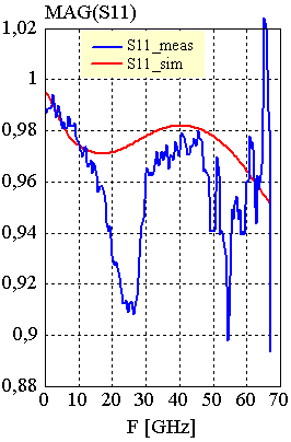
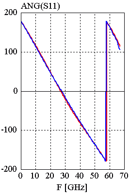
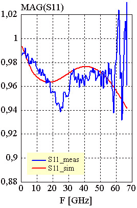
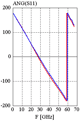
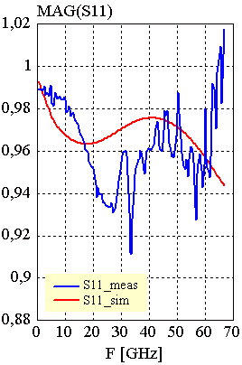
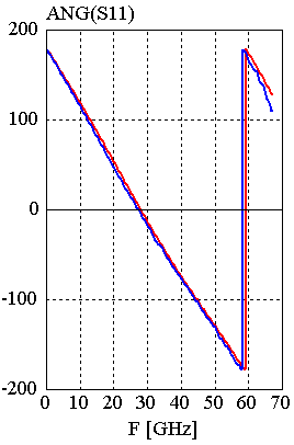
One main result of the comparison between measured and simulated circuits is, that the agreement of more complex circuits, which utilize a great number of different passive coplanar elements, is much better than the evaluation of very simple circuits like these series of shorts. The reason for that phenomenon lies in the measurement technique and its calibration. We used commercial LRM standards on ceramics. Some structures on the calibration substrate are very similar to our 'simple' circuits, so that little inaccuracy while calibrating the system or measuring the circuits may lead to incorrect measurement data. Nevertheless, results become more and more better with an decreasing of the line. In comparison with the first two examples, the last configuration has a line width of 25mm (instead of 200mm) of the shorting termination strip. The simulation shows a more lossy behavior of the circuit with a 25mm strip, which could not be proofed, if we consider only the measured data.
Configuration: 50W1 CPW configuration feed line length = 1mm WG = 200mm |
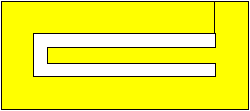
Configuration: 50W2CPW configuration feed line length = 1mm WG = 200mm |
Configuration: 50W1CPW configuration feed line length L= 1mm WG = 25mm |
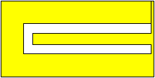
[close window] | [C_SHORT] |