| [to index] | [close window] | [C_SHORT Verification] |


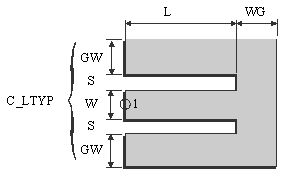
L = Length of transmission line connected to the coplanar short end.
WG = Width of the ground plane at the shorted end (WG=0 ® infinite ground plane)
C_LTYP = ID of coplanar transmission line applied at port 1
C_SUB = ID of coplanar substrate definition
C_GRID = ID of simulation control data
TEMP = ID of element temperature definition used for noise computation
WG = 0.5.n.DL* n=1,2,3,...
* ) see C_GRID for information on DL
- The C_SHORT module represents a short circuited coplanar line. The dimensions of the line connected to the short are defined using data item addressed by C_ LTYP. L is the length of the connected coplanar line.
- WG is the extension of the ground plane at the end of shorted line.
- A negative value for L can be meaningful during the simulation. In such cases, the automated layout generation works incorrectly and the generated layout has to be edited manually. The minimum value for L depends on the metal layer oversizes in the currently selected C_LAYER. In case of DEFAULT foundry, L should be greater than or equal to max(|cond_os|, |cond2_os|).
- For WG =0, infinite ground plane at the shorted end is assumed for the simulation.
- If L1 and L2 in selected C_GRID are not set to -1 (auto sizing), the minimum values for L1 and L2 are:
L1min=W+2*S+2*GW
L2min=8*DL{C_GRID}+WG
- See notations in chapter 4 (Important Note!) for the correct selection of the C_LTYP.
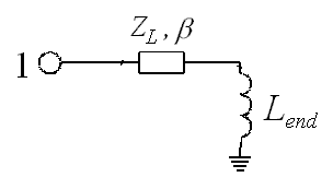
For the modeling of the C_SHORT element, an equivalent inductance is used. The value of this inductance is derived from quasi-static FD-calculations. The connected line at the port is modeled as a C_LIN element and is represented by its characteristic impedance ZL and phase constant b. There is no limitation due to the length of connected line (L).

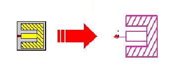
- 1. For L=0 only the ground plane at the end of line is drawn.
- 2. If CEN_MET and GND_MET in the selected C_LTYP are at different levels, the ground plane at shorted end is built in both metal level .
- 3. If the parameter GW_DEF in C_PROCES is set to a positive non-zero value, this value is used as ground width for layout generation.