|
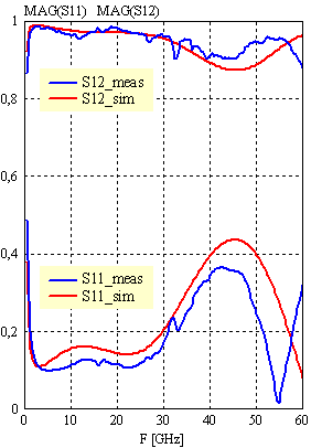
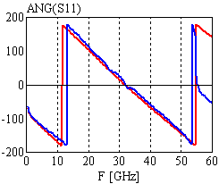
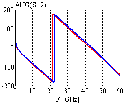
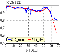
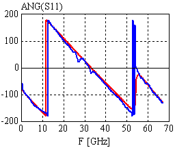
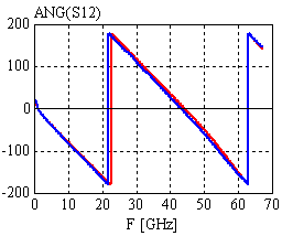
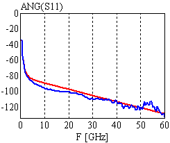
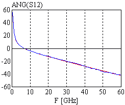
Configuration: CPW line configuration at the ports: 50W1 lines, len=1mm; airbridges: TYPE=2, BW=50, BS=14, BG=8mm; MIM: LC=300mm, DC=200nm, er=7.45; top and bottom electrodes of the MIM have the same line width |

|
|
|
|
Configuration: CPW line configuration at the ports: 50W1 lines, len=1mm; airbridges: TYPE=2, BW=50, BS=14, BG=8mm; MIM: LC=300mm, DC=200nm, er=7.45; top and bottom electrodes of the MIM have the same line width |

|
|
|
|
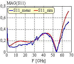
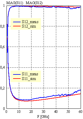
Configuration: 50W line configuration at the ports: LEN=30, W=40, S=30, D=150mm; MIM: ® top electrode: W=40, S=30, D=150mm ® bottom elect.: W=44, S=28, D=150mm LC=145mm, DC=130nm, er=7 |

|
|
|
| [close window] | [C_MIM] |