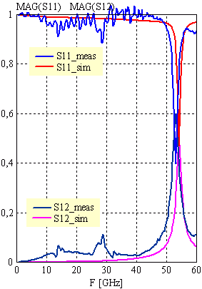
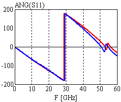
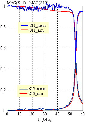
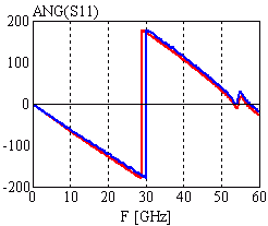
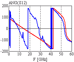
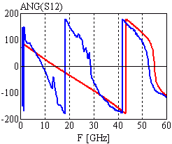
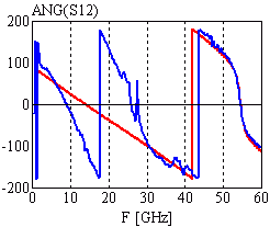
The circuit behavior is like a l/2-resonator (len=1mm). The resonance frequencies are fr_meas=53GHz and fr_sim=54.2GHz. The deviation between measurement and simulation results from the calculated eeff, which is a static value for the FD-simulator (40W5 CPW: eeff_static = 6.66). The real eeff is frequency dependent and was simulated with a spectral domain analysis: eeff(f=60GHz) = 7.106. The theoretical resonance frequencies for these values are fr(eeff=6.66) = 58.39GHz, fr(eeff=7.106) = 56.65GHz, if the whole circuit consists of 40W5 lines. Although it proofs the difference between measurement and simulation.
Configuration:
50W3 lines (len=1mm) at the ports, 40W5 (len=1mm, d=240mm) CPW resonator in the middle of the circuit, separated by a gap (GAP=25mm) |
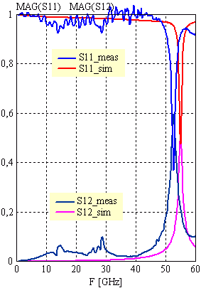
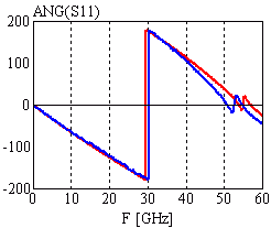
Configuration:
50W3 lines (len=1mm) at the ports, 70W7 (len=1mm, d=202mm) CPW resonator in the middle of the circuit, separated by a gap (GAP=25mm) |
Configuration:
50W3 lines (len=1mm) at the ports, 50W3 (len=1mm) CPW resonator in the middle of the circuit, separated by a gap (GAP=5mm); discretization size DL=2.5mm, iteration error BOUND = 1*10e-4 |
[close window] | [C_GAP] |