[close window] [180o Hybrid Coupler with Lumped Elements]

Traweling Wave Amplifier


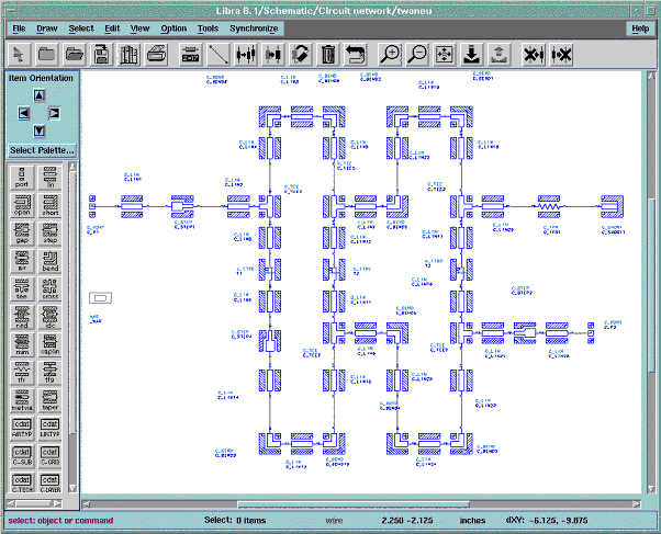
The third example is a three stage Traweling Wave Amplifier. The schematic of the circuit is shown in Figure 9-13. It shows the use of coplanar discontinuities with airbridges. The layout of the circuit is shown in Figure 9-14. Figure 9-15 shows some details of this layout with the used FET. The simulated S-Parameters of the circuit are plotted in Figure 9-16. A gain of nearly 7dB could be achieved. The corresponding project directory $EESOF_DIR/ examples/coplan_v2310_prj.


Figure 9-13. Schematic of the Coplanar Traweling Wave Amplifier
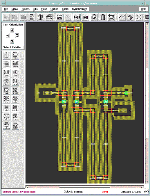


Figure 9-14. Complete Layout of the Coplanar Traweling Wave Amplifier
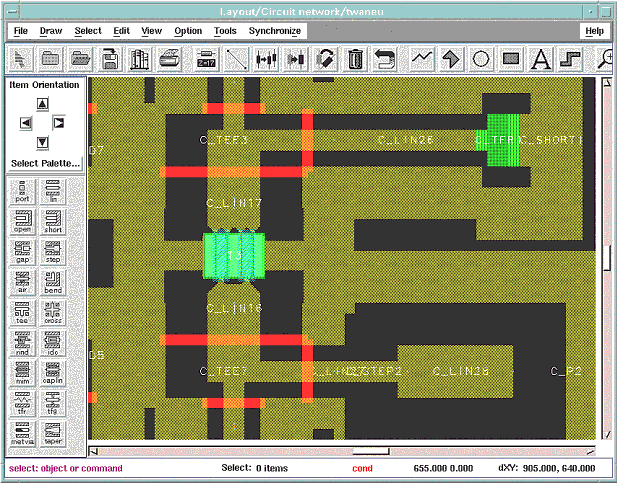


Figure 9-15. Partial Layout of the Coplanar Traweling Wave Amplifier
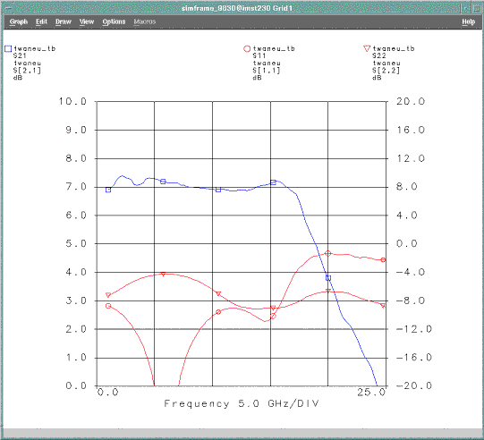


Figure 9-16. S-Parameter of the Coplanar Traweling Wave Amplifier


[close window] [Coplanar Interdigital Coupler]