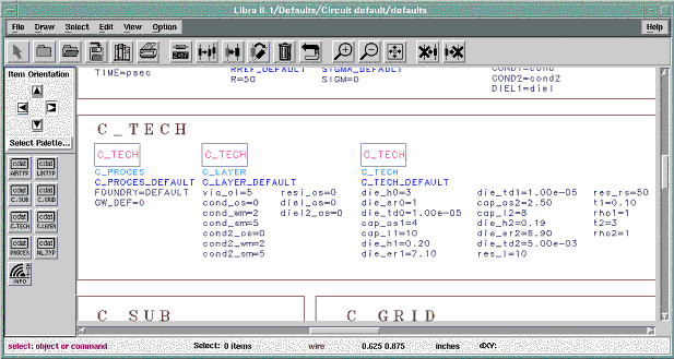
Figure 9-1. Definition of technology parameters in data items C_PROCES, C_TECH and C_LAYER
| [close window] | [8 Verification] |
In this chapter, a short tutorial will be introduced for the handling of COPLAN for ADS. Four examples are presented and the simulated results for two examples are compared with measurements. All examples documented here are available on the CD-ROM of COPLAN for ADS and will be installed automatically by the start of installation program in directory $EESOF_DIR/examples/coplan_v2310_prj.
The first step is the definition of data items. We begin with the so called technology data items. These are C_PROCES, C_TECH and C_LAYER (see chapter 4 for more detail). Figure 9-1 shows the definition of these items defaults window. Please note that the name of C_PROCES data item is always C_PROCES_DEFAULT. In this item the name of used foundry (parameter FOUNDRY) and a default ground width (parameter GW_DEF) as global parameter for width of ground planes has to be specified. The standard packet of COPLAN for ADS consists of an arbitrary foundry named DEFAULT foundry. If no other foundry is available, the only name allowed for FOUNDRY is DEFAULT. If GW_DEF is greater than zero, this value will be used as ground width for all elements, otherwise the ground width defined in related C_LTYP is used. Please note, that for the simulation always the ground planes defined in C_LTYPs is used.
The foundry process data are defined in C_TECH and C_LAYER. Since the DEFAULT foundry is used, the name of these data items must be C_TECH_DEFAULT and C_LAYER_DEFAULT. The parameter in these data items can be specified by the user and help him to adapt the DEFAULT foundry to his specific requirements. Please note that data in C_LAYER_DEFAULT are used only by the layout generation whereas the data in C_TECH_DEFAULT are used by both simulation and layout generation (see C_TECH and C_LAYER in chapter 4). The technology data items must be defined only once.

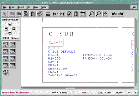
The data for the substrate used has to be defined in C_SUB. The use of name C_SUB_DEFAULT enable the user to select this item as default by entering an * in the select box of related element. However, it is also possible to use several C_SUB data items in a design. Figure 9-2 show the definition of substrate parameter using C_SUB. As is already described in chapter 4 (C_SUB), the distance to the upper and lower cover can be automated by selecting the value –1 for H1 and H3. If conductor backed coplanar waveguides have to be simulated, the parameter H1 must be set to 0, in this case the value of ER1 is ignored. The value ER3 can be also used for the simulation of packaging effects.
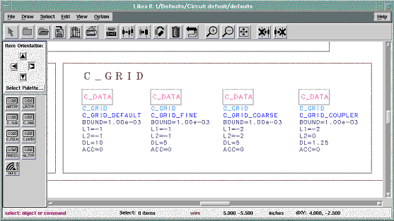
For the definition of simulation control parameters, C_GRID data items must be defined. Since the simulation accuracy and simulation time depends strongly on the grid size DL, it is recommended to use several C_GRID items for different elements (see Figure 9-3). Usually for lines and simple discontinuities, a coarse grid is already sufficient, whereas for more complicated elements like C_IDC and C_RIND, a finer grid is required. The box size (parameter L1 and L2) can be specified by the user, but it is recommended to use auto sizing by selecting values –1 or –2 for these parameters. A value –2 is sufficient for a first simulation run and also during the optimization. For the final simulation a value –1 should be used. The parameter ACC indicates the tolerated deviation of structure dimensions from grid mesh. A value ACC=0 is recommended in order to avoid any differences between layout and simulation. However, if the user wish to simulate a structure with non-compatible dimensions, a value between 0 and 100 can be defined for ACC (see C_GRID in chapter 4 for more information on ACC)
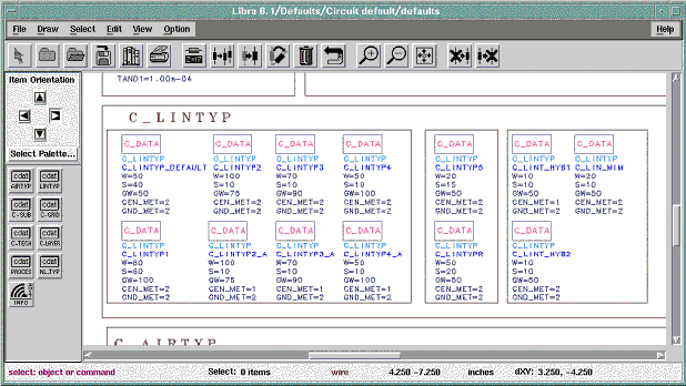
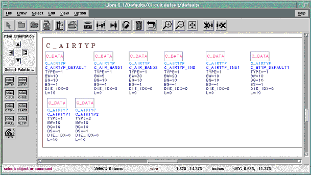
All coplanar elements in COPLAN for ADS consists of coplanar lines at ports. The parameter of these lines must be defined in C_LINTYP data items (see Figure 9-4). For junctions and for spiral inductor, air-bridges are necessary in order to suppress the excitation of higher order modes (see Theoretical Background/Useful Hints in chapter 2). The type and dimensions of such bridges must be defined in C_AIRTYP data items (see Figure 9-5). Depending on the topology and size of circuit a series of C_LINTYPs and C_AIRTYPs are necessary. Please note that a C_LINTYP_DEFAULT and a C_AIRTYP_DEFAULT should be always defined in order to avoid error messages by the directly generation of layouts from layout window.
| [close window] | [Lumped Element Bandpass Filter] |