- Coplanar Traveling Wave Amplifier
 |
|
Coplanar Traveling Wave Amplifier
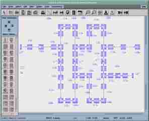
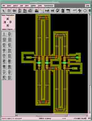
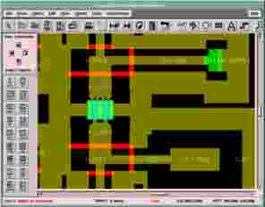
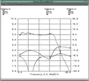
The example documented here is a three stage Trawling Wave Amplifier. The schematic of the circuit is shown in Figure 9-13. It shows the use of coplanar discontinuities with airbridges. The layout of the circuit is shown in Figure 9-14. Figure 9-15 shows some details of this layout with the used FET. The simulated S-Parameters of the circuit are plotted in Figure 9-16. A gain of nearly 7dB could be achieved.

Figure 9-13. Schematic of the Coplanar Trawling
Wave Amplifier
 |
 |
| Figure 9-14. Complete Layout of the Coplanar Trawling Wave Amplifier | Figure 9-15. Partial Layout of the Coplanar Trawling Wave Amplifier |

Figure 9-16. S-Parameter of the Coplanar Trawling Wave
Amplifier