| Parameter | Description |
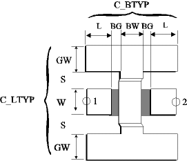
| C_LTYP | ID of coplanar transmission line applied at ports 1 and 2 |
| C_BTYP | ID of air-bridge type definitions |
| C_SUB | ID of coplanar substrate definition |
| C_GRID | ID of simulation control data |
| TEMP | ID of element temperature definition used for noise computation |
| L1min=W+2S+2GW |
| L2min=8DL+BW+2BG |
For the modeling of the C_AIR element, a p-network is used. The parasitic electric field due to the air-bridge is represented by the lossy shunt capacitance Cp. The inductance L is used for the modelling of the current disturbance in the area of the bridge. The metallic losses within the bridge itself are taken into account by the use of a frequency dependent resistance R.
| The equivalent circuit parameters are derived from quasi-static FD-calculations. The connected lines at ports are modeled as C_LIN elements and are represented by their characteristic impedance ZL and phase constant b. There is no limitation due to the length of connected lines (L in selected C_BTYP). | 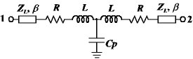 |