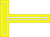
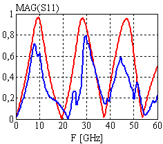
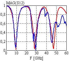
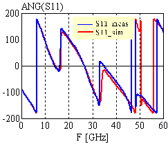
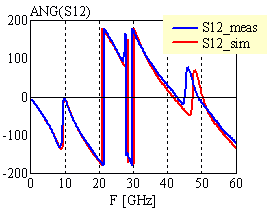
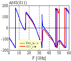
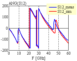
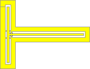
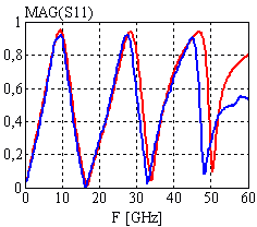
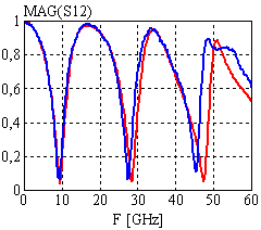
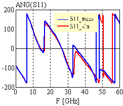
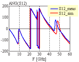
| Configuration: T-junction with resonator stub utilizing 50W1 CPW configuration; stub length = 3mm; feed line length = 1mm; no airbridges used |
 |
|
|
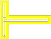
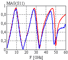
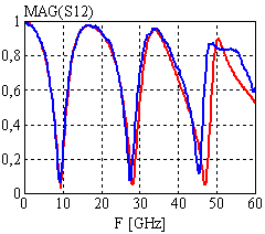
| Configuration: T-junction with resonator stub utilizing 50W1 CPW configuration; stub length = 3mm; feed line length = 1mm; 3 airbridges used at the nodes of the T-junction with the parameter: TYPE=2, bg=8, BW=50, BS=14mm |
|
|
|
| Configuration: T-junction with resonator stub utilizing 50W1 CPW configuration; stub length = 3mm; feed line length = 1mm; 3 airbridges used at the nodes of the T-junction with the parameter: TYPE=1, bg=14, BW=50, BS=8mm |
|
|
|
| [close window] | [C_TEE] |