|
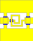
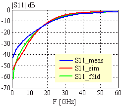
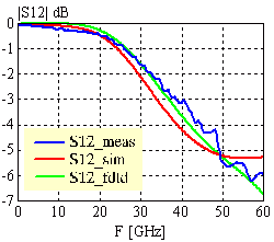
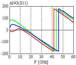
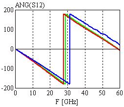
Configuration: 50W1 CPW lines with airbridges of TYPE=2, BW=50mm, BS=14mm, bg=8mm feed line length = 400mm inductor configuration:N = 1.5, WF=25mm, SF=20mm, IDIA1=95mm, IDIA2=50mm, S=30mm, BW=25mm, BS=14mm, BG=8mm |
|
|
|
|
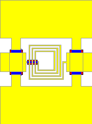
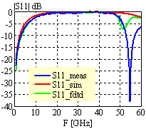
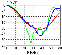
Configuration: 50W1 CPW lines with airbridges of TYPE=2, BW=50mm, BS=14mm, BG=8mm feedline length = 400mm inductor configuration:N = 3.5, WF=8mm, SF=7mm, IDIA1=92mm, IDIA2=77mm, S=33.5mm, BW=8mm, BS=14mm, BG=8mm |
|
  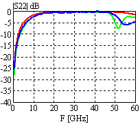
|
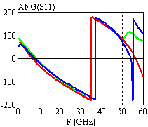 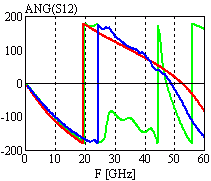 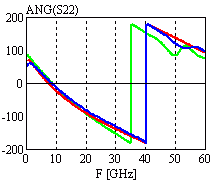
|
|
Configuration: 50W CPW lines (W=50, S=40, D=50mm) inductor configuration: N = 9.5, WF=10mm, SF=8mm, IDIA1=125mm, IDIA2=108mm, S=20mm, BW=10mm, BS=10mm, BG=10mm |
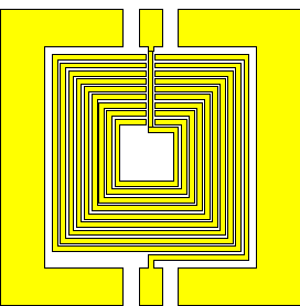
|
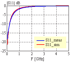 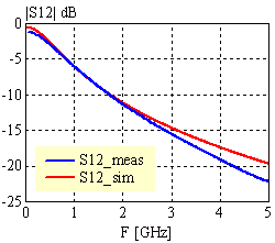
|
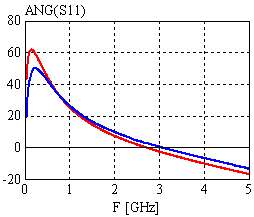 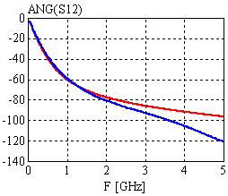
|
| [close window] | [C_RIND] |