|
Configuration: Feed lines configuration: 50W1, length=1mm; Airbridges: TYPE=2, BW=50, BS=14, BG=8mm MS-Substrate: h=150mm, w=100mm IDC: N=2, WF=25mm, SF=20mm, LF=300mm width of feed line: W=50mm spacing to ground: SGF=30mm (90mm) gap between ground and feed line: S=20mm |
 |
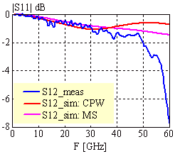 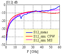
|
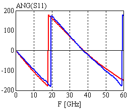 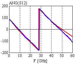
|
|
Configuration: Feed lines configuration: 50W1, length=1mm; Airbridges: TYPE=2, BW=50, BS=14, BG=8mm MS-substrate: h=150mm, w=100mm IDC: N=2, WF=25mm, SF=20mm, LF=300mm width of feed line: W=50mm min. spacing to ground: SGF=30mm (90mm) gap between ground and feed line: S=20mm |

|
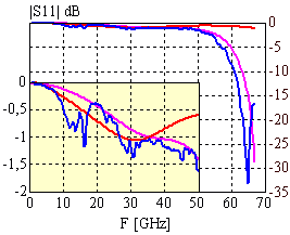 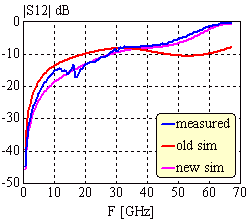
|
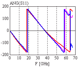 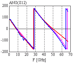
|
|
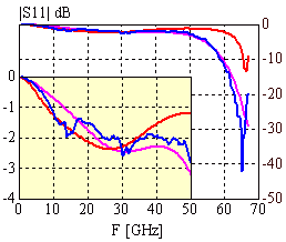
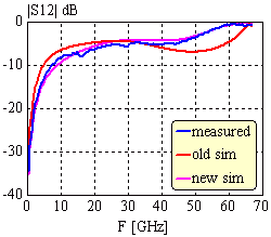
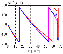
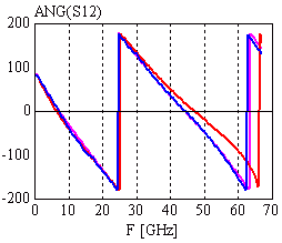
Configuration: Feed lines configuration: 50W1, length=1mm; Airbridges: TYPE=2, BW=50, BS=14, BG=8mm IDC: number of fingers: N=5, WF=25mm, SF=20mm, LF=300mm width of feed line: W=50mm min. spacing to ground: SGF=30mm gap between ground and feed line: S=20mm |

|
|
|
| [close window] | [C_IDC] |