|
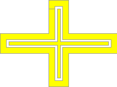
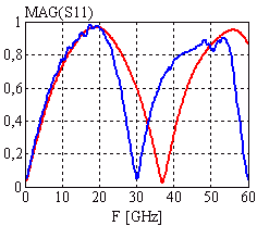
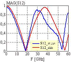
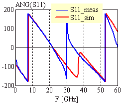
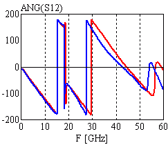
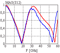
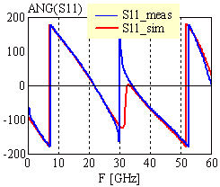
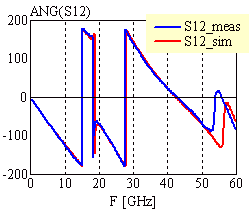
Configuration: Cross junction with resonator stub utilizing 50W1 CPW configuration; stub length = 1.5mm; feed line length = 1mm; no airbridges used |
|
|
|
|
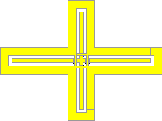
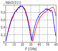
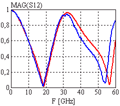
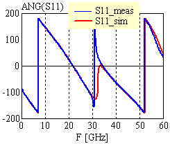
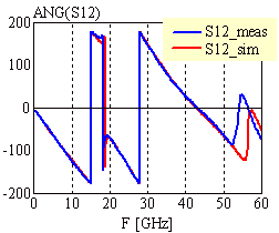
Configuration: Cross junction with resonator stub utilizing 50W1 CPW configuration; stub length = 1.5mm; feed line length = 1mm; 4 airbridges used at the nodes of the cross with the parameters: TYPE=2, BG=8, BW=50, BS=14mm |
|
|
|
|
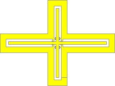
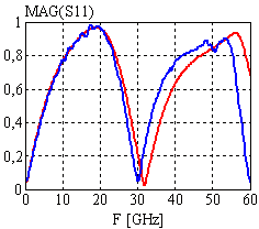
Configuration: Cross junction with resonator stub utilizing 50W1 CPW configuration; stub length = 1.5mm; feed line length = 1mm; 4 airbridges used at the nodes of the cross with the parameters: TYPE=1, BG=14, BW=50, BS=8mm |
|
|
|
| [close window] | [C_CROSS] |