Please take detailed information about layout handling within ADS from corresponding ADS handbooks. The layout of each element is given in chapter 5. In this section only few important comments are included for the correct dealing.
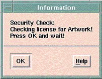
- The key word for the layout feature is checked by FLEXlm software during the first run of automatic layout generation procedure (Synchronize from schematic window). This takes a while. Please pay attention to the messages which are then reported in your shell window:
Checking License for CPW_ALA . . .
Furthermore, you get following message:
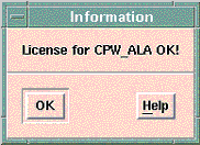
License OK for CPW_ALA2.3
Checking License for CPW_ALA . . .
License OK for CPW_ALA2.3

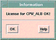
If checking was successful, you receive the following message:
 or
or 
- In some cases the first synchronization can fail. In such cases, please clear the layout (File/Clear Layout) and start the synchronization again.
- Please make sure that you have the correct unit in your layout window. Otherwise you may get incorrect connection pin sizes. In this case, you can select the correct pin size using the menu point (Option/Preferences ...).
- The name of used layer for the DEFAULT-foundry are stored in the file “layer.lay”. If this file does not exist in your current project directory, please copy and rename the file “default.lay” in $EESOF_DIR/config directory as follows:
cp $EESOF_DIR/config/default.lay layout.lay
- You should clear the current layout in the Layout Window (File/Clear Layout), before synchronizing a new design. Otherwise some overlaps may caused during the layout generation .
- Using the edit function „Mirror“ in the Layout or Schematic Window can lead to an overlapping of some layout sections. Avoid therefore this function if possible.
- Because of the fact that the width of the ground planes of every coplanar element can be selected separately, an overlapping of some ground sections can be resulted. To avoid this problem, a default ground width (GW-DEF) can be defined in the C_PROCES data item. A negative value for GW_DEF activates the ground width selected by each element.