| COPLANAR TRANSMISSION LINES | ||
| NAME | PHISICAL | Equivalent Circuit |
| C_2COUP . . . C_10COUP 2 to 10 Coupled Coplanar Lines |
 |
See Following Descriptions |
Table 6-1. Coplanar Coupled Lines in COPLAN for ADS
| [close window] | [5.4 Description of Coplanar Elements] |
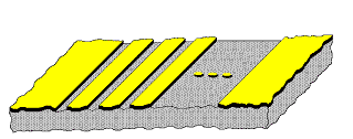
At the present, the palette of “Coplanar Coupled Elements” consists of 2 to 10 multiple coupled coplanar lines (9 elements). IMST plans to add more elements into this palette in the future.
Table 6-1 shows the elements in this palette. The name of each element begins with a “C_”, it follows the number of coupled center lines and the string “COUP”; for example: 2 coupled coplanar lines (C_2COUP) or three coupled coplanar lines (C_3COUP) etc. The coupled center lines are surrounded by finite ground planes. Up to 10 lines with different line widths and metallization layers as well as different slots between lines can be defined in a data item C_NL_TYP (see Coplanar Data Items).
| COPLANAR TRANSMISSION LINES | ||
| NAME | PHISICAL | Equivalent Circuit |
| C_2COUP . . . C_10COUP 2 to 10 Coupled Coplanar Lines |
 |
See Following Descriptions |
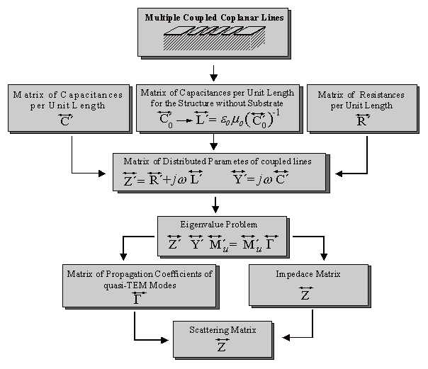
Coupled lines are often used in order to realize directional couplers or interdigitated filters. For the fast and accurate simulation of coupled coplanar lines, an analysis method with CAD capability is developed. This method allows the consideration of finite substrate and metallization thickness as well as the influence of finite ground planes. Figure 6-1 shows the schematic description of the used analysis method based on the theory of multi-conductor systems.

A quasi-static finite difference method [2.4] is applied to the system of multiple coupled coplanar lines that forms the coupler cross section. The use of a smart non-equidistant discretization as well as the utilization of the successive over relaxation (SOR) for the solution of the Laplace's difference equation leads to a very fast numerical determination of charge and surface current distribution on conductors. From these quantities, the distributed parameters of coupled lines, it means the capacitance, inductance and resistance matrices per unit length (C´, L´ and R´) can be calculated.
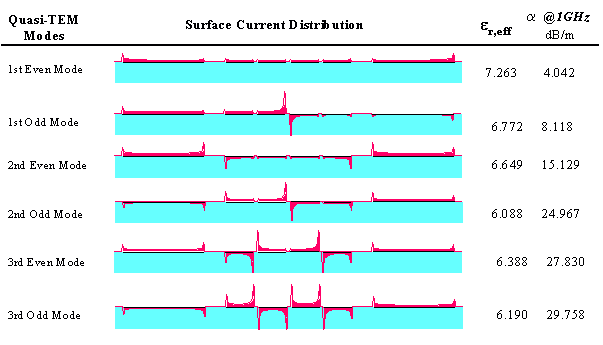
The matrix of series impedance as well as the matrix of the shunt admittance per unit length of coupled section are used for the solution of the eigenvalue problem which delivers the propagation coefficients of propagating quasi-TEM modes and the impedance matrix of the coupled line system. Figure 6-2 shows the propagation characteristics (effective dielectric constant er,eff, attenuation a and surface current distribution) calculated for the six possible quasi-TEM modes of four coupled coplanar lines. Using the normalized impedances at ports, the scattering matrix of the coupled lines can be calculated.

| [close window] | [Coplanar Coupled Lines C_2COUP . . . C_10COUP] |