[close window] | [2.4 Finite Difference Formulation] |
From the electrical field inside the shield, the total charge on the metalization (Qtotal) and the charge per unit length on the connecting transmission lines (Q') are calculated. Since the potential difference between the inner conductor and the ground plane is known to be V, the capacitance(s) (Ceq) associated to a given structure is then calculated as the difference between the total charge and the charge per unit length of the virtual transmission lines connected at ports:
,where l is defined as the virtual distance between the back-transformed reference planes of the discontinuity and the magnetic walls (see reference [2.2]).
The calculation of capacitive model parameters is demonstrated here in case of an interdigitated capacitor. The procedure is shown in Figure 2-5. Two different potential configurations are used for the calculation of shunt capacitances Cp1 and Cp2 as well as the couple capacitance Cg. By the so called even mode simulation, the center lines and the fingers of the capacitor are set on the same potential of 1Volt whereas the ground planes are set to zero Volt. The solution of the Laplace´s equation leads to the field distribution on the metalization. The shunt capacitances Cp1 and Cp2 are calculated from the charge distribution on the conductors.
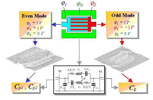
For the calculation of the coupling capacitance Cg, a so called odd mode simulation is necessary. In this case, the fingers of the capacitor are set to opposite potentials of 1Volt and -1Volt. The ground planes are set to zero Volt. After the calculation of the potential distribution, the charges on conductors are used for the determination of the capacitance Cg.