| [to index] | [close window] | [C_OPEN Verification] |


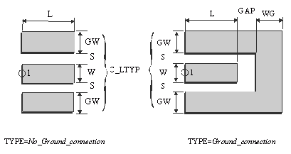
L = Length of transmission line connected to the coplanar open end.
GAP = Spacing between the open end and ground planes (only for TYPE= Ground_Connection)
WG = Width of the ground plane at the open end. (WG=0 ® infinite ground plane, only for TYPE=Ground_Connection)
TYPE = Type of open (see illustration)
C_LTYP = ID of coplanar transmission line applied at port 1
C_SUB = ID of coplanar substrate definition
C_GRID = ID of simulation control data
TEMP = ID of element temperature definition used for noise computation
GAP = 0.5.n.DL* n=1,2,3,...
WG = 0.5.n.DL* n=1,2,3,...
* ) see C_GRID for information on DL
- The C_OPEN module represents an open at the end of a coplanar line. The dimensions of the line connected to the open are defined in data item addressed by C_ LTYP. L is the length of the connected coplanar line.
- GAP is the distance between the open end and ground planes and WG is the extension of the ground plane at the end of line.
- A negative value for L can be meaningful during the simulation. In such cases, the automated layout generation works incorrectly and the generated layout has to be edited manually. The minimum value for L depends on the metal layer oversize in the currently selected C_LAYER. In case of DEFAULT foundry, L should be greater than or equal to max(|cond_os|, |cond2_os|).
- For WG =0, infinite ground plane at the open end is assumed.
- TYPE indicates the form of open end. There are two types of open ends as shown in the above illustration.
- If TYPE= No_Ground_Connection is selected, the parameters WG and GAP are ignored.
- If L1 and L2 in selected C_GRID are not set to –1 or –2 (auto sizing), the minimum values for L1 and L2 are:
L1min=W+2S+2GW
L2min=8DL+GAP+WG
- See notations in chapter 4 (Important Note!) for the correct selection of C_LTYP.
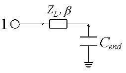
For the modeling of the C_OPEN element, an equivalent capacitance is used. The value of this capacitance is derived from quasi-static FD-calculations. The connected line at the port is modeled as a C_LIN element and is represented by its characteristic impedance ZL and phase constant b. There is no limitation due to the length of connected line (L)

- If TYPE=No_Ground_Connection and L=0, only a port symbol is generated as layout. For L=0 and TYPE=Ground_Connection only the ground planes at the end of line is drawn.
- If the parameter GW_DEF in C_PROCES is set to a positive non-zero value, this value is used as ground width for layout generation.