Coplanar Coupled-Lines Data Definitions C_NL_TYP
Symbol :

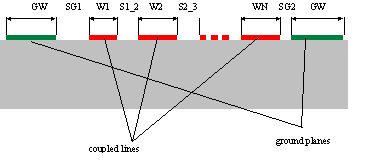
Illustration :

Parameters :
GW = Width of ground planes
GND_MET = Identification of metal level for the ground planes (Used for layout only)
SG1 = Slot between first line and left ground plane
SG2 = Slot between last line and right ground plane
W1 = Width of line 1
LEVEL1 = Identification of metal level for line 1
S1_2 = Slot between line 1 and line 2
W2 = Width of line 2
LEVEL2 = Identification of metal level for line 2
S2_3 = Slot between line 2 and line 3
W3 = Width of line 3
LEVEL3 = Identification of metal level for line 3
S3_4 = Slot between line 3 and line 4
W4 = Width of line 4
LEVEL4 = Identification of metal level for line 4
S4_5 = Slot between line 4 and line 5
W5 = Width of line 5
LEVEL5 = Identification of metal level for line 5
S5_6 = Slot between line 5 and line 6
W6 = Width of line 6
LEVEL6 = Identification of metal level for line 6
S6_7 = Slot between line 6 and line 7
W7 = Width of line 7
LEVEL7 = Identification of metal level for line 7
S7_8 = Slot between line 7 and line 8
W8 = Width of line 8
LEVEL8 = Identification of metal level for line 8
S8_9 = Slot between line 8 and line 9
W9 = Width of line 9
LEVEL9 = Identification of metal level for line 9
S9_10 = Slot between line 9 and line 10
W10 = Width of line 10
LEVEL10 = Identification of metal level for line 10
Range of Usage :
W1 to W10 = 0.5.n.DL* n=2,3,4,...
S1_2 to S9_10 = 0.5.n.DL* n=1,2,3,...
SG1, SG2 = 0.5.n.DL* n=1,2,3,...
GW = 0.5.n.DL* n=2,3,4,...
LEVEL1 to LEVEL10 = 1 or 2 (DEFAULT-Foundry)
GND_MET = 1 or 2 (DEFAULT-Foundry)
* ) see C_GRID for information on DL
Notes/Equations/References :
- The geometrical dimensions of coupled coplanar lines are defined in the C_NL_TYP data item.
- The coupled line parameters (W1 to W10, S1_2 to S9_10, SG1, SG2 and GW) must be chosen in a way that metallization corners lie on the grid (see Range of Usage). However, if the user specify a maximum deviation from grid size ACC (see C_GRID for details), the simulator can adapt the incompatible structure parameters into the grid by changing these parameter slightly (warnings will be reported). For ACC=0 (no deviation from grid) the simulator reports error and the next compatible value will be recommended in the error message. Note that these changes are not considered by automatic layout generation.
- Depending on number of lines of related element, some parameters in C_NL_TYP are ignored. For example for 5 coupled coplanar lines (element C_5COUP), only the parameters with an index less than 5 are used (it means W1 to W5, LEVEL1 to LEVEL5 and S1_2 to S4_5). The parameters GW, SG1, SG2 and GND_MET are always used.
- In the presented version all center lines must have the same metal level LEVEL.
- In present version, GND_MET is used for layout generation only. For the simulation, GND_MET is set equal to LEVEL1.

