Coplanar Inter Metal Via (no Step) C_METVIA
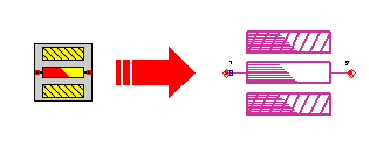
Symbol :

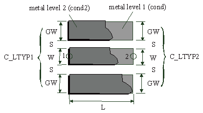
Illustration :

Parameters :
L = Length of via-section
C_LTYP1 = ID of coplanar transmission line applied at port 1
C_LTYP2 = ID of coplanar transmission line applied at port 2
C_SUB = ID of coplanar substrate definition
C_GRID = ID of simulation control data
TEMP = ID of element temperature definition used for noise computation
Notes/Equations/References :
- The C_METVIA module is introduced to connect two coplanar transmission lines with different metal levels. The dimensions and metal level of connected lines are defined in data items addressed by C_LTYP1 and C_LTYP2 (see C_LINTYP). L is the length of connection region.
- The C_METVIA module is not able to calculate a step. As a result, lines addressed by C_LTYP1 and C_LTYP2 must have the same line width W and the same slot width S.
- The minimum value for L depends on the overlap defined in the currently selected foundry. In case of DEFAULT foundry, L should be greater than or equal to via_ol (see C_LAYER).
- If L is set to zero or negative value, the automated layout generation works incorrectly if an via_ol (see C_LAYER) is defined for the inter metal via. In this case the generated layout has to be edited manually.
- For the simulation of C_METVIA, the metallisation thickness of the center line is set to the sum of metallisation thickness of applied lines.
- See notations in chapter 4 (Important Note!) for the correct selection of the C_LTYP1 and C_LTYP2.
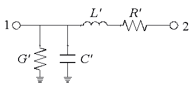
Equivalent Circuit :
For the modeling of the C_METVIA element, a distributive equivalent circuit is used and the model parameter are derived from quasi-static FD-calculations. The DC and RF losses (represented by R´) due to the skin effect are calculated using the surface current distribution on the conductors. The dielectric loss of the substrate material (represented by G´, see also C_SUB) is also taken into account.
Layout :
- In the case of interactive layout generation (directly from layout window), selecting the C_METVIA module causes an error message due to the fact, that both C_LTYP1 and C_LTYP2 have the same metal level by default. In order to get a correct layout, the user has to attach a valid pair of C_LTYP's to the C_METVIA.
- If the parameter GW_DEF in C_PROCES is set to a positive non-zero value, this value is used as ground width for layout generation.


