| [to index] | [close window] |


BOUND = Maximum iteration error used by iterative solver
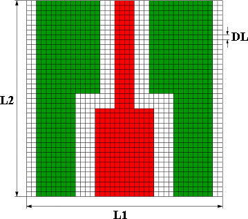
L1 = Width of shielding box (L1=-1, -2 ® auto sizing)
L2 = Length of shielding box (L2=-1, -2 ® auto sizing)
DL = Size of smallest grid element
ACC = Maximum deviation from grid in %
BOUND 1E-06 £ BOUND £ 1E-02
L1,L2 see notes of related element
DL > 0
ACC 0 £ ACC £ 100
- In this data item, grid and simulation control data are defined for the implemented Finite Difference-Solver.
- The maximum iteration error for the applied “Over Relaxation Method” can be selected using the parameter BOUND. Following table shows the influence of this parameter on simulation time and accuracy of results for a coplanar cross junction. The time and error values are related to the results for BOUND=10-6. A value of 10-3 is recommended for a first run simulation. For the final analysis, a BOUND=10-4 is always sufficient (see chapter 2 for more detailed information on this subject).
No. BOUND Simulation Time
Related to No. 5Error Related to
No. 51 10-2 9 % 60 % 2 10-3 28 % 2.5 % 3 10-4 54 % 0.3 % 4 10-5 77 % 0.03 % 5 10-6 100 % 0 %
Table 1. Effect of iteration error BOUND on simulation time and accuracy
- The shielding box sizes effect the accuracy of the results. In order to keep these effects as small as possible, L1 (Box width) and L2 (Box depth) should be as large as possible. The simulator adapts the box sizes on the structure automatically if L1 and L2 are set to –1 or –2. The following table shows the possible combinations for L1 and L2 (for BOUND=10-4) and their effect on the accuracy and simulation time.
No. L1 L2 Simulation Time
Related to No.4Error Related
to No. 51 -2 -2 14 % 8 % 2 -1 -2 36 % 7 % 3 -2 -1 36 % 6 % 4 -1 -1 100 % 0 %
Table 2. Effect of box sizes L1and L2 on simulation time and accuracy
- In cases where user like to investigate the shielding effects on structure characteristics, Box sizes can be specified manually. For such applications, the minimum values for L1 and L2 (given in the notes of the related element) and their compatibility to the grid (see below notes) are. Manually selected box sizes could lead to errors if the user optimize the structure dimensions, since in this case the box size is not automatically adapted to the changed dimensions.
- The parameter L2 is ignored for the elements: C_LIN, C_METVIA, C_TFG, C_TFR, C_MIM, C_CAPLIN.
- DL is the external grid size, whereas the internal grid size is DL/2. The metalization edges of the structure have to lie on grid points, this means that the structure dimensions have to be an integer multiple of DL/2. However, if the user specify a maximum deviation from grid size ACC, the simulator can adapt the incompatible structure dimensions into the grid by changing these dimensions slightly (warnings will be reported). For ACC=0 (no deviation from grid) the simulator reports error and the next compatible value will be suggested in the error message. These changes are not considered by automatic layout generation. In order to avoid any discrepancies between simulation and layout, a value of ACC=0 is recommended.
- The value for metallization thickness tn (n=1,2) and dielectric height die_hn (n=0,1,2) can be independent from grid size DL. However, for these two parameters, the ratio t/DL and die_h /DL should be between 0.2 and 5.0. Otherwise, the accuracy of the simulation can not be guaranteed.
| [to index] | [close window] |