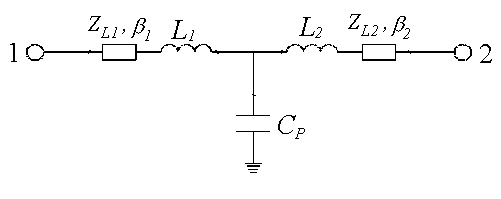
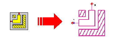
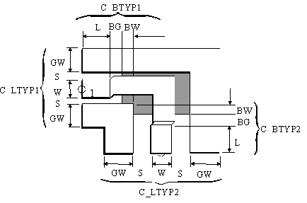
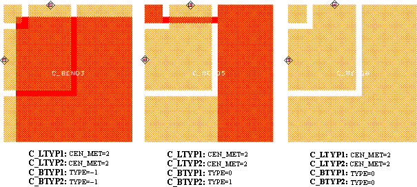
The C_BNED module represents a rectangular bend between two coplanar lines. The dimensions of lines are defined using data items addressed by C_ LTYP1 and C_TYP2. The dimensions of the air-bridges at ports are defined in data items addressed by C_BTYP1 and C_BTYP2.
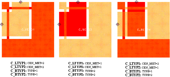
If the line types defined by C_LTYP1 and C_LTYP2 have different center line levels (CEN_MET) an inter metal via is automatically included in the bend structure (see Layout).
For a bend without air-bridges, the applied line types must have the same center level CEN_MET.
The keyword TYPE of the selected C_BTYP controls if the structure contains bridges or not. Normally bridges are necessary to suppress odd mode excitation. Note that due to the applied air bridge additional feed lines with a length L defined in the selected C_BTYP are connected to the bend structure. This additional feed lines connect the reference planes with bridges (see Illustration). There is no line between bridges and bend structure itself .
The keyword TYPE of the bridge applied at a port and the center line level CEN_MET of the line type applied on the same port can not have the same value.
If the keyword TYPE in one of the C_BTYPs is set to -1, the TYPE of the other C_BTYP has to be also -1.
Both C_BTYP must have the same DIE_IDX.
If the Keyword TYPE in one of the C_BTYP data items is set to 0 and the parameter BG and BW are nonzero values, these parameter will not set automatically to zero. This means that the total size of the discontinuity is not changed if only the TYPE is set to zero (see Layout).
If L1 and L2 in selected C_GRID are not set to -1 (auto sizing), the minimum values for L1 and L2 are:
L1min= W1+2*S1+2*max(GW1, BW2+BG2+4*DL{C_GRID})
L2min= W2+2*S2+2*max(GW2, BW1+BG1+4*DL{C_GRID})
See notations in chapter 4 (Important Note!) for the correct selection of the C_LTYP and C_BTYP.
