Coplanar Bridgetype Data Definition C_AIRTYP
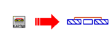
Symbol :

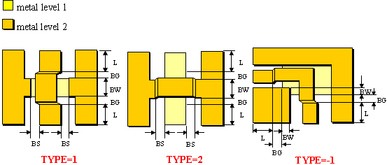
Illustration :

Parameters :
TYPE = identifies the metal level of bridge (TYPE=0 ® no bridge )
BW = bridge width
BG = bridge gap
BS = bridge spacing (BS= -1 ® BS = S of connected Linetype )
DIE_IDX = index to the dielectric layer definition for bridges in selected foundry
L = length of feed line connected to the bridge
Range of Usage :
TYPE = 0, 1, 2, -1 (see illustration)
BW = 0.5.n.DL* n=1,2,3,...
BG = 0.5.n.DL* n=0,1,2,3,...
BS = 0.5.n.DL* n=1,2,3,... (or –1)
DIE_IDX = (0, 1 or 2 in DEFAULT foundry)
* ) see C_GRID for information on DL
Notes/Equations/References :
- The C_AIRTYP data item describes the construction of air bridges used in junctions and spiral inductors.
- The value of TYPE defines the metal level of the bridge (the connection of the two ground planes). Two different options (TYPE=1 and TYPE=2) are available for the air bridge element (C_AIR) and all other structures which contain bridges (C_BEND, C-TEE, C_CROSS and C_RIND). In addition, for the junction elements C_BNED, C_TEE and C_CROSS a special bridge type TYPE= –1 is also available (see illustration). TYPE=0 switches off the bridge definition. TYPE=0 is not allowed for C_AIR and C_RIND.
- The correct chose of TYPE depends on value of CEN_MET in C_LINTYP of the connected lines. TYPE and CEN_MET can not have the same value.
- If TYPE=0 is selected, the parameter BW and BG are not set automatically to zero! In this case, the bridge removed but a piece of coplanar line with the length of (BW+2BG+2L) will remain. This ensure that the reference planes of the element are not changed if the air bridge is switched off.
- If TYPE=0 or BS = -1 or BS>S, BS will be set automatically equal to S (S is the slot of the line type C_LINTYP connected to the bridge). In case of C-RIND, BS is always set equal to the slot between the turns of inductor (ST in C_RIND).
- The dielectric used under the bridge is defined in the foundry data item C-TECH (parameter die_ern, die_hn, and die_tdn with n=0,1,2). DIE_IDX indicates the corresponding index n of dielectric parameter in C_TECH data item. In case of DEFAULT fondry DIE_IDX can have the values 0,1 or 2. For example, if DIE_IDX=0, die_h0 will be the bridge height, die_er0 the dielectric constant of the dielectric under the bridge and die_td0 the tangent loss of this dielectric. See C_TECH for more information on dielectric layer parameters.
- L is the length of the coplanar line connected to the bridge at ports of related element (see illustration for TYPE= –1). The configuration of the feed line connected to the bridge is given in the C_LINTYP data item of the corresponding element. For example, in the above illustration bridges are used in C_BEND element, each air bridge is connected with a piece of coplanar line of length L at ports of C_BEND. In case of C_AIR, the same line length L is connected to the both ports (as shown in the illustration). L is ignored in case of C_RIND.
- A zero or negative value for L can be meaningful during the simulation. For L<0, the automated layout generation works incorrectly and the generated layout has to be edited manually.

